


The safety of mechanical excavators is related to the technical measures to eliminate or reduce the risks caused by major dangers, dangerous states or dangerous events in the use, operation and maintenance of earthwork construction. What are the inspection standards for mechanical excavators? How are mechanical excavators inspected?
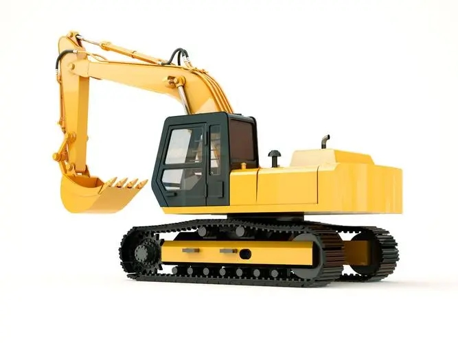
Mechanical excavator
Mechanical excavators refer to excavators whose upper structures are operated by wire ropes. They mainly use drag shovels, front shovels or grab buckets for excavation operations; use tamping plates to tamp materials; use hooks or balls for crushing operations; and use special working devices and attachments. Carry out material handling.
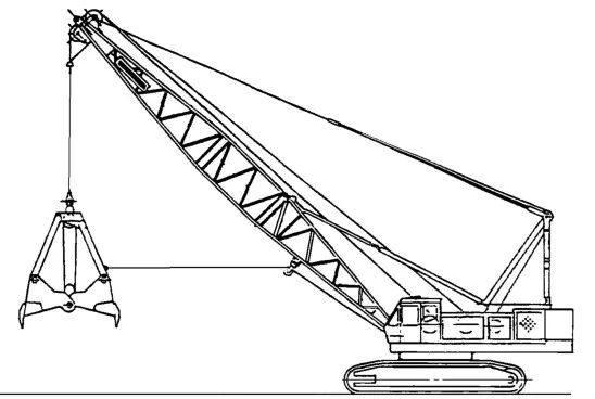
Crawler mechanical excavator with grab equipment
Mechanical excavator inspection standard requirements
01 Mechanical excavator inspection-driver operating position inspection
-Equipment
A driver's cab should be installed at the driver's position of a ride-on machine.
Machines with a working mass greater than 1,500 kg and a driver's position should be equipped with a driver's cab. Machines with a working mass less than or equal to 1,500 kg are not required to be equipped with a driver's cab.
Earthmoving machinery should be designed to ensure that adequate protective devices are installed when used in applications where there is a risk of flying debris (e.g. using hydraulics).
-Minimal activity space
The minimum movement space for drivers should comply with ISO 3411.
The minimum space for the driver's position and the location of the controls should comply with ISO 6682
-Moving parts
Provisions should be made to avoid accidental contact from the driver's position with moving parts such as wheels, belts or working equipment or attachments.
-Engine exhaust
The exhaust gas from the engine should be kept away from the driver and the air inlet of the cab
- Purchase and deposit of driver’s license
A space should be provided near the driver's position to safely store the driver's manual or other operating instructions. If the driver's position cannot be locked or there is no driver's cab, the space should be lockable.
-Sharp edges
There should not be any exposed sharp edges or corners on the driver's workspace (such as the ceiling, inner instrument panel and passage to the driver's position).
-Climate conditions at the driver's position
The driver's cab should protect the driver from foreseeable adverse weather conditions. Preparations for ventilation systems, adjustable heating systems and glass defrosting systems should be installed in accordance with regulations.
-Hard pipes and hoses
The cab is equipped with liquid pressure greater than 5 MPa or temperature greater than 60 C and hoses.
-Basic entrances and exits
A basic access opening shall be provided, the dimensions of which shall be in accordance with ISO 2867.
- Alternate entrance and exit
An alternate entrance/exit shall be provided on a different side from the primary entrance/exit. Its dimensions shall comply with ISO 2867. This could be a window or another door that can be opened or moved without keys or tools. If the entrance can be opened from the inside without a key or tools, use a latch. Breakable glass doors and windows of suitable size may also be considered as suitable alternative exits, provided that the necessary escape hammer is provided in the cab and placed within the driver's reach.
-Ventilation system
The ventilation system should be able to provide fresh air to the driver's cab with a flow rate of not less than 43 m/h. Filters shall be tested in accordance with SO 10263-2.
-Defrost system
The defrosting system should provide front and rear window defrosting devices, such as through a heating system or a dedicated defrosting device.
-Supercharging system
If a cab with a pressurization system is provided, the pressurization system shall be tested in accordance with the provisions of SO 10263-3 and shall provide a relative indoor pressure of not less than 50 Pa.
-Doors and windows
Doors, windows and flaps should be securely restrained in their intended operating positions. Doors should be held in their intended operating position by rigid restraints designed to maintain the safe opening of the basic entrance and exit in the intended operating position, and the restraints should be easily released from the driver's position or driver's entrance platform.
Car windows should be installed with safety or other materials with the same safety performance.
Front windows should be equipped with electric wipers and washers.
The water tank of the window washer should be easily accessible.
-Internal lighting
The driver's cab should be equipped with a fixed internal lighting device, which should still function after the engine is turned off, so that the driver's position can be illuminated and the driver's manual can be read.
- Driver's protective shield
Mechanical excavators should be able to install protective structures for the driver (top guards and front guards). The manufacturer should provide protective structures (top guards and front guards), which should be selected by the user based on the existing application risks.
-Falling Object Protective Structure (FOPS)
Except for the exceptions specified in ISO3449, square cranes expected to be used in locations with falling objects hazards should be designed to be able to install a falling object protective structure (FOPS).
02 Mechanical Excavator Inspection - Driver's Controls and Indicators
-Start and stop device
Earthmoving machinery should be equipped with starting and stopping devices (such as keys), and the starting system should be equipped with protective devices to prevent unauthorized use.
Earth-moving machinery shall be so designed that when the engine is started or stopped, it is impossible to move the machine, working equipment and attachments without starting controls.
-Unexpected operation
Control devices that may cause danger due to accidental operation should be arranged or disabled or protected in accordance with the principle of minimizing risks. In particular, when the driver enters and exits the driver's position, the device that disables the control should be self-activating, or It is forcibly stimulated and activated by relevant devices.
-pedal pedal
There should be suitable size, shape and adequate spacing between them. The treads should have a non-slip surface and be easy to clean. If the pedals of earth-moving machinery and the pedals of automobiles have the same functions (clutch, braking and acceleration), in order to avoid the danger caused by mixing, the pedals should be arranged in the same way.
-Emergency landing of attachments
If the engine stalls, it should be possible to:
· Lower the working device/attachment to the ground/rack;
· The lowering of the work unit/attachment is visible from the position where the driver activates the lowering control:
· Eliminate residual pressure in each hydraulic and pneumatic circuit of work equipment/accessory equipment that may cause risks.Provisions for lowering attachments and means for removing residual pressure may be located outside the driver's position and shall be described in the driver's manual
-Uncontrolled movement
Movement of machines and working devices or attachments from fixed positions, except when operated by the driver, due to slipping or slowing (e.g. caused by leakage) or when the power supply is interrupted, shall be controlled within a range that does not create a risk to exposed persons.
-Visual displays/control panels, indicators and symbols
· The driver should be able to see necessary indications of the normal functioning of the machine from the driver's position, day or night. Glare should be minimized.
· Control indicators for normal operation and safety of the machine should comply with the provisions of ISO 6011 on safety and related matters.
· Symbols for visual display/control devices on earthmoving machinery shall comply with the provisions of ISO 6405-1 or S 6405-2, as applicable.
- Control devices of ride-on machines that are not intended to be operated from the ground shall be provided with means to minimize the possibility of lifting the control device from the ground.
- Non-ride-on machines should be equipped with a holding operation device that stops the operation of the machine and the dangerous movement of the implement when the driver releases control. Controls should be designed to take into account the risk of accidental movement of the machine towards the operator.
03 Mechanical excavator inspection-steering system inspection
- The steering system should ensure that the steering maneuver is consistent with the intended steering direction specified in ISO 10968.
- Forward/reverse belt-covered machines The steering system of a belt-covered machine traveling at a speed exceeding 20 km/h should be gentle.
04 Mechanical excavator inspection-swing brake system inspection
Mechanical excavators should be equipped with swing operation and parking brake systems.
05 Mechanical excavator inspection-lifting system inspection
- Forced control (raise/lower)
The lifting system of the mechanical excavator should be equipped with a brake. The brake should be activated immediately after releasing the handle or pedal. The braking system should automatically activate in the event of loss of power or forced control decline, and should not affect the stability of the excavator operation. Braking The system should be able to maintain the rated load specified in 4.8
-Free fall operation
The hoisting system of a mechanical excavator shall be equipped with a brake and shall be activated immediately under the following conditions:--The corresponding operation of the foot pedal;
Release the hand lever.
Brakes shall be designed to provide continuous braking of a moving load.The guide should be designed to prevent the wire rope from rising or falling out of control
-Switch
When switching from forced control operation to free drop operation, there should be no drop of the load.
-boom
The boom of a mechanical excavator should be protected from rebound in the event of sudden unloading. The boom should be equipped with a limit switch to avoid reverse overloading.
The connections (bolts) between the various parts of the boom should be designed to allow installation and removal without the need for personnel to stand under the boom.
-Wire rope
The safety factor of the mechanical excavator wire rope should be determined.
-Wire rope drum and wire rope pulley
· The design and manufacture of wire rope drums and wire rope pulleys should prevent damage to the wire rope and slippage or detachment of the wire rope guide bushing.
· The ratio of wire rope drum diameter to wire rope diameter should be at least 20:1.
· The ratio of the wire rope pulley diameter to the wire rope diameter measured at the rope groove should be at least 22:1. Dragline guides, guide pulleys and auxiliary wire ropes are excluded.
· Crimping rim, the edge of the winch drum should be at least 1.5 times the diameter of the wire rope.
06 Mechanical excavator inspection-restriction device inspection
-Load moment limiter
In material handling conditions, the hoisting system and boom hoisting system should be equipped with a load moment limiter to avoid overload. The load moment limiter should be set to the rated load specified in 4.8, with a tolerance of 10%. After the load moment limiter is operated, the load moment should be reduced. 4.7.2 Lift the limit switch.
In material handling conditions, mechanical excavators should be equipped with limit switches for lifting movements. After the limit switch is activated, the boom should be able to lower.
-Limit switch for boom lift system
The boom lifting system of a mechanical excavator should be equipped with a limit switch to avoid reverse overloading of the boom. After the limit switch is activated, the boom should be able to lower.
07 Mechanical excavator inspection-stability inspection
- Earthmoving machinery with working devices and attachments, including optional devices, designed and manufactured shall provide sufficient stability under the maintenance, assembly, disassembly and transportation operating conditions specified by the manufacturer in the driver's manual. Devices used to increase the stability of earthmoving machinery in operating mode should be fitted with an interlock or one-way valve to hold the hose in place if it fails or becomes full of oil.
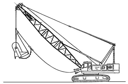
- Dragline bucket, the operating capacity of the mechanical excavator in dragline operation shall be the smaller of the following two:
a) 75% of the calculated overturning load P;
b) Maximum lifting capacity of winch.
Dragline bucket capacity calibration shall be determined by the manufacturer
-Grapple and shovel
The operating capacity of a mechanical excavator in grab and shovel conditions should be the smaller of the following two:
· Based on 66% of the calculated overturning load P;
· Maximum lifting capacity of winch.
The capacity calibration of the shovel shall be determined in accordance with ISO 7546 and the capacity calibration of the grab bucket shall be determined by the manufacturer.
Post time: Dec-19-2023