


Standard specifications: GB/T 42825-2023 General technical specifications for electric scooters
Specifies the structure, performance, electrical safety, mechanical safety, components, environmental adaptability, inspection rules and marking, instructions, packaging, transportation and storage requirements of electric scooters, describes the corresponding test methods, and defines the corresponding terms and definition.
General requirements for electric scooter inspection
1. Under normal use, reasonably foreseeable misuse and failure, electric scooters should not be dangerous. Danger includes but is not limited to the following situations:
-The heat generated causes material deterioration or personnel burns;
-Hazards such as burning, explosion, electric shock, etc.;
-During the charging process, toxic and harmful gases are released;
-Personal injuries caused by breakage, deformation, looseness, movement interference, etc. of the vehicle or components
1. The safety of lithium-ion batteries should comply with the regulations of GB/T 40559. The initial capacity, high temperature capacity and low temperature capacity of the battery should comply with the regulations of SJ/T 11685. Batteries that are reused should not be used.
2. The safety of the charger should comply with the regulations of GB 4706.18, and it should be compatible with the battery system of the electric scooter; the connector of the electric scooter charging port should be able to prevent misalignment and reverse plugging.
3. The combustion classification of circuit boards and non-metallic casings surrounding batteries should not be lower than V-1 in GB/T 5169.1.
General requirements for electric scooter inspection
Electric scooter inspection structure and appearance requirements
-Sharp edges: Use visual and finger touch methods to check whether there are parts of the rider’s body that are accessible to the electric scooter. During normal riding, transportation and maintenance, there should be no exposed sharp edges where the rider’s hands, legs and other bodies may come into contact.
-Protrusion: The electric scooter is in an upright position. Visually inspect the end of the handlebar cross tube: Use a vernier caliper to measure the length of the end of the bolt after assembly.
Rigid protrusions on electric scooters should meet the following requirements:
● For rigid protrusions that may injure the rider, the ends of the protruding parts should be protected with appropriately shaped protectors (for example: the end of the handle bar should be protected with a silicone or rubber protective sleeve);
● For bolts, the length beyond the mating part of the thread is less than the nominal diameter of the bolt.
-Movement clearance: Use a pass-and-stop gauge to measure the movement clearance of the electric scooter. In addition to the wheels (the gaps between the wheels and their support systems, wheels and fenders), suspension systems, braking systems, brake handles, and folding mechanisms, the movement clearance of the electric scooter should be less than 5 mm, or greater than 18 mm.
-Internal wiring: Use visual methods to check the internal wiring of the electric scooter. Internal wiring should meet the following requirements:
● The wires are firmly fixed and do not bear excessive pressure or looseness. Two or more wires in the same direction are supported together; the wires are placed on components without sharp angles and edges; Note: Excessive pressure will cause obvious deformation of the guide wires.
● There is an insulating sleeve at the wire connection;
● When the wire passes through the metal hole, the wire or metal hole is equipped with insulating sleeve components.
Electric scooter inspection performance requirements
1. Maximum speed
The inspector drives the test vehicle to accelerate from a standstill, keeping the speed control handle at the maximum opening, so that the driving speed reaches the maximum vehicle speed and remains unchanged, and passes through a 5 m test interval, recording the speed value passing through the test interval. The test is carried out 2 times and the average value is taken. The maximum speed of an electric scooter should be within ±10% of the company’s stated maximum speed, and should not exceed 25 km/h.
2. Motor start
Connect a DC ammeter in series to the motor input end of the test vehicle. When the speed of the test vehicle is lower than 3 km/h, adjust the speed control knob to the maximum opening, check the value of the ammeter, and detect the operation of the motor. Increase the speed of the test vehicle to more than 3 km/h, use electric driving and then brake. After the speed of the test vehicle drops to 1 km/h~3 km/h, adjust the speed control knob to the maximum opening. , check the value of the ammeter and detect the operation of the motor. When the speed of an electric scooter is less than 3 km/h, its motor should not output power.
3. Braking performance
Use visual methods to inspect the braking system of the test vehicle. Electric scooters should have two or more (including two) braking systems, and at least one of them should be a mechanical braking system that fully generates the average deceleration 5.2.4.2. When using all braking systems, the fully developed average deceleration should be ≥3.4 m/s’; when only using the mechanical braking system, the fully developed average deceleration should be >2.5m/s”
Electric scooter inspection electrical safety inspection
1. Maximum output voltage
Fully charge the battery, let it sit for 2 hours, and measure its voltage with a DC voltmeter. The maximum battery output voltage should be less than or equal to 60 V.
2. Short circuit protection
Check whether the battery charging circuit and battery output circuit of the test vehicle are equipped with protective devices such as fuses according to the circuit diagram. Check the charging circuit, battery output circuit, or circuit board if necessary. The charging circuit and battery output circuit of electric scooters should be equipped with protection devices such as fuses.
3. Insulation resistance
The insulation resistance between the power circuit, control circuit and exposed conductive parts of an electric scooter should be greater than 2mΩ.
4. Fever
Fix the test vehicle on the test bench, apply the maximum load specified by the manufacturer, and measure the temperature of the handlebar’s grip, pedals, exposed cables, connectors and other areas until the low battery alarm occurs. Use visual methods to check the protective measures for parts where the surface temperature is greater than 57 C and easily accessible to cyclists; check the high temperature warning signs marked on prominent locations such as motors and braking systems.
The heating of electric scooters should meet the following requirements:
During the test, the surface temperature of the parts that the rider continues to contact (such as handlebars, pedals, etc.) shall not be greater than 43°C; a brake system with an operating temperature greater than 60°C shall have exposed parts or obvious surrounding parts Mark warning signs; 60
During the test, except for the braking system, the surface temperature of parts that are easily accessible to riders (such as cables, connectors, etc.) is not greater than 57C; if there are parts with a surface temperature greater than 57C, protective measures are in place. .
5. Charging lock
Use the adapter charger to charge the test vehicle battery when it is powered off. During the battery charging process, turn on the power switch and check the operation of the test vehicle’s motor. The electric scooter’s motor should not be running while the battery is charging.
6. Brake power off
Electric scooters should have a braking and power-off function. When the electric scooter is braking, the motor input current should be less than or equal to its current without torque output (standby current) within 3 seconds.
7. Charging interface protection
Car charging interface, check whether the anti-reverse connection is effective. Check whether the charging interface of the test vehicle and the output interface of the charger are the only connection methods; if not, try to connect the charger to the test in reverse direction. The charging interface of the electric scooter should have protective design functions to prevent reverse connection and electric shock.
Electric scooter inspection machinery safety inspection
1. Pedal static strength
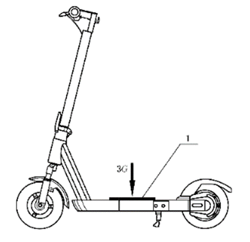
Through a support with a cross-sectional size of 150 mmX150 mm, apply 3 times the maximum load (G) specified by the manufacturer at the center point of the pedal and maintain it for 5 minutes. Then remove the load, let it sit for 10 minutes, and measure the permanent deformation of the stressed part of the pedal. The permanent deformation of the force-bearing part of the pedal of an electric scooter should not be greater than 5 mm.
2. The vehicle load drops
On the pedals of the test vehicle, apply and secure the maximum load (G) specified by the manufacturer. Fix the rear wheel, raise the front wheel, and when the front wheel is 200 mm away from the test surface, drop it on a flat surface of mixed or similar hardness, as shown in the figure, repeat the drop 3 times.
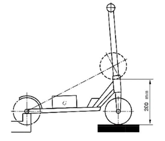
After the test, the electric scooter should not catch fire, explode, or leak. Its main load-bearing structure should have no obvious damage or deformation, and it should drive normally.
The end of the handlebar cross tube should be equipped with a handle cover or handle cover, which should be able to withstand a pull-off force of 70 N. For the quick-release handlebar cross tube, after assembling the quick-release part and the handlebar cross-tube, apply force in the direction of the quick-release handlebar cross-tube. There should be no separation between the quick-release part and the handlebar cross-tube.
4. Handlebar static load strength
Carry out handlebar strength test according to the following method
- Resistance to downward force: Fix the test vehicle horizontally so that it remains vertical during the test. At the same time, a vertical load of (250 ± 5) N is applied to the middle position of the two grips and maintained for 5 minutes.
- Resist upward force: Fix the test vehicle upside down. At the same time, a vertical load of (250 ± 5) N is applied to the middle position of the two grips and maintained for 5 minutes.
- Resist forward force; fix the test vehicle horizontally so that it remains vertical during the test. At the same time, a forward load of (250 ± 5) N is applied to the middle position of the two grips and maintained for 5 minutes.
- Resistance to backward force: Fix the test vehicle horizontally so that it remains vertical during the test. At the same time, a backward load of (250 ± 5) N is applied to the middle position of the two grips for 5 minutes.
After the test, visually inspect the handlebars and locking devices. There should be no obvious deformation of the handlebars; there should be no cracks or breaks in the handlebars and their locking devices, and they should operate and lock normally.
4. Handlebar fatigue strength
Fix the test vehicle horizontally so that it cannot move and the handlebars cannot rotate. Apply a force of 270 N along the upper and rear (above/rear), that is, the 45° direction of the vertical direction, evenly distributed on both sides of the handle bar 25 mm from the end, and then repeat in the opposite direction (below/front) Operation, apply force in two directions for one cycle, and repeat 10,000 cycles at a frequency not greater than 1 Hz. After the test, use visual methods to check the condition of the handlebars. There should be no visible cracks, damage, obvious deformation or looseness in various parts of the handlebars.
Fix the test vehicle horizontally so that its body cannot move and the handlebars and front wheels can freely rotate around their axes. Apply a torque of 10 N·m to rotate the handlebar from one extreme position to the other, repeating 10,000 times at a frequency not greater than 0.5 Hz. After the test, there should be no visible cracks, damage, obvious deformation or looseness in various parts of the handlebars, bendable wires and their sheaths.
6. Vehicle vibration
After the test, the battery of the electric scooter should not catch fire, explode, or leak, there should be no cracks or breaks in any part of the mechanical structure, and all electrical components should function normally.
7. Vehicle fatigue strength
Place and fix the maximum load specified by the manufacturer at the center of the pedal of the test vehicle, and apply a load of 5 kg each at the center of the two handlebars. Fix the rear wheel of the electric scooter and place the front wheel on a roller with a diameter of not less than 700 mm. Three bosses with a height of 5 mm are evenly installed on the surface of the roller (the top width is 20 mm, the uphill direction is 17, the downhill direction is 45). The roller travels 50 km at a speed of 2 m/s. After the test, visually inspect each test vehicle Check whether there are any abnormalities in the parts. When testing the multi-track test vehicle, the bosses should be staggered to prevent two or more wheels from passing the bosses at the same time.
After the test, the electric scooter should meet the following requirements:
- No visible cracks or breaks in any part of the frame and no separation of any part of the frame;
-If a gap occurs, it will not affect the work of the components and user safety.
Electric scooter inspection parts inspection
1. Folding locking device
The requirements for folding locking devices are as follows.
- The folding locking device should be opened through two consecutive operations, and the second operation relies on the rider to perform and maintain the first operation to take effect (such as a safety lock).
- Orikan locking devices should clearly indicate whether the device is in the loose or locked position.
-When the folding locking device is in the locked state, it should not be accidentally loosened or unlocked while riding. A force of 150N or a torque of 2.2N m is applied in the direction in which the folding locking device is most likely to be opened by a single operation. There should be no unlocking fracture or permanent deformation.
- The folding locking device shall not break or permanently deform when subjected to a locking force of 250 N.
-The folding locking device should not come into contact with moving parts during riding.
2. Telescopic mechanism
Use test gauges and pressure gauges to check the structure, clearance, and displacement of the telescopic mechanism. The telescopic mechanism shall meet the following requirements:
-Each telescopic mechanism has a locking device;
-The gap after the telescopic mechanism is locked shall not be larger than 5 mm;
- After the telescopic mechanism is locked, a force of 250 N is applied along the telescopic direction for 1 minute without relative displacement.
3. Pedal
Use a length measuring instrument to measure the anti-slip area of the pedal of the test vehicle. The anti-slip area of the pedal of the electric scooter should not be less than 150 cm.
4. Battery
Connect the DC regulated power supply to the test vehicle and turn it on to check the operation of its motor. Electric scooters should be powered by original batteries. Original batteries refer to batteries that can be produced by other manufacturers with authorization or permission from the original manufacturer of the electric scooter.
5. Wheels
Use universal measuring tools to measure the wheel outer diameter and tire width of the test vehicle.All wheel sizes of electric scooters shall comply with the following requirements
-Wheel outer diameter 2125 mm;
-Tire width >25 mm.
6. Warning device
Use visual methods to inspect the lighting devices, reflectors or light signaling devices of the test vehicle. The front of the electric scooter should be equipped with a lighting device, and the left and right sides of the front, rear and rear should be equipped with reflective devices. Electric scooters should be equipped with a horn device, and the sound pressure level of the horn device should be 75 dB(A)~95 dB(A).
7. Main control switch
Electric scooters should be equipped with an obvious, easy-to-reach and error-proof main control device to turn on and off the driving power, and the device should be triggered by the rider’s autonomous behavior.
Other inspection points for electric scooter inspection
1. Instructions
-The instruction manual of the electric scooter should contain relevant instructions and information on the use, operation, and maintenance of the electric scooter, including at least the following content.
● Security and restrictions:
● Use this product in compliance with relevant laws, policies, regulations and other instructions
● Information on protective measures for users to wear helmets, knee pads, elbow pads and other protective equipment;
● Detailed instructions for the operation, storage and charging of electric scooters, including but not limited to environmental conditions, road conditions, etc.;
● The operating environment and potential risks that may lead to dangerous situations when using and driving the electric scooter indicate the possible danger of high temperature burns;
● Restrictive condition information such as user age and physical condition
-Product parameters and usage:
● The size and mass of the electric scooter, as well as the load or load capacity limitations; the enclosure protection level of the electric scooter;
● How to charge electric scooters:
● The location and specifications of the fuse and other protective devices of the electric scooter, as well as their markings on the simple circuit diagram;
● How to store and use electric scooters;
● The driving range of electric scooters and their test methods and conditions
-Maintenance:
Maintenance information for electric scooters, as well as prohibition of unauthorized disassembly and repair by users, etc.
-other information:
-Product performance standards;
-After-sales service contact information such as service phone number or email address:
-Other safety warnings.
2. Logo
-Product logo
The product mark of an electric scooter should contain the necessary information to inform users and its specifications, at least the following information:
● Product name and model;
● Manufacturer’s name or trademark, manufacturer’s address;
● Maximum output voltage;
● Maximum load;
● Maximum speed
-Safety warning signs
The electric scooter body should have necessary safety warning signs to inform users of safe use. When necessary, safety warning signs on precautions when using, operating, and maintaining electric scooters should be provided. Safety warning signs include but are not limited to:
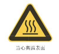
● Warnings and signs for hot parts;
A mark indicating the locking position of the safety lock of the folding locking device;
● The logo of the electric scooter charging interface;
● Electric scooters are marked with “Only use original charger” and other similar warning signs in a conspicuous position.
● Read the warning messages or icons in the manual before use.
-Packaging logo
The outer packaging of the product should have the following markings:
● Manufacturer’s name and trademark;
● Product name;
●Model;
● Standard number (can also be marked on the product or manual);
● Box size (length x width x height) and volume;
● Quantity;
● Storage and transportation icons such as “Handle with caution” and “Afraid of getting wet”;
● Factory date or production batch number.
2. Packaging
-Ex-factory products should be accompanied by product certificates, packing lists, and product description materials.
- External cartons or other packaging boxes should be bundled securely.
Post time: Oct-24-2023