


National mandatory standards and IEC have technical requirements for the marking, anti-shock protection, structure, electrical performance, mechanical performance, etc. of plugs and sockets for household and similar purposes. The following are the inspection standards and methods for plugs and sockets.
1. Appearance inspection
2. Dimensional inspection
3. Protection against electric shock
4. Grounding measures
5. Terminals and Headers
6. Structure of the socket
7. Aging-resistant and moisture-proof
8. Insulation resistance and electrical strength
9. Temperature rise
10. Breaking capacity
11. Normal operation (life test)
12. Pull-out force
13. Mechanical strength
14. Heat resistance test
15. Screws, current-carrying parts and their connections
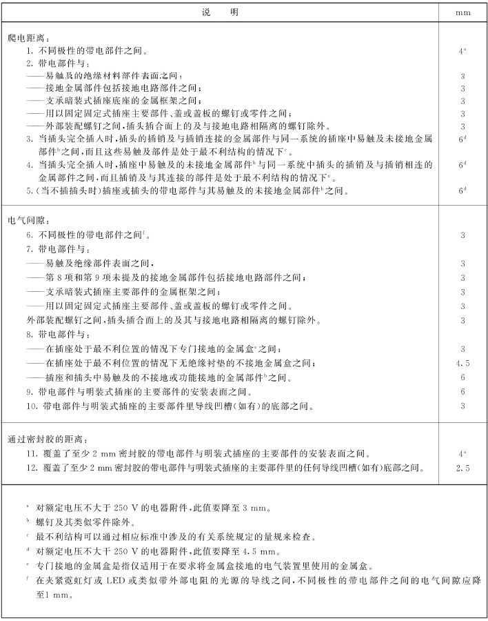
16. Creepage distance, electrical clearance, penetration insulation sealing distance
17. Abnormal heat resistance and flame resistance of insulating materials
18. Anti-rust performance
1. Appearance inspection
1.1 The main components of the product should have the following marks:
-Rated current (amps)
-Rated voltage (volts)
- Power supply symbol;
-The name, trademark or identification mark of the manufacturer or seller;
-Product number
-Certification mark
1.2 The correct symbols should be used on the product:
1.3 For fixed sockets, the following markings should be marked on the main components:
-Rated current, rated voltage and power supply properties;
-The name or trademark or identifying mark of the manufacturer or seller;
-The length of insulation that should be stripped before the conductor is inserted into a screwless terminal (if any);
- If the socket is only suitable for connecting hard wires, there should be a sign that the screwless terminal is only suitable for connecting hard wires;
-Model number, which can be a catalog number.
1.4 Appearance quality: The surface of the socket should be smooth, the shell should be uniform, and there should be no pores, cracks, indentations, bumps, damage, spots, or dirt; the metal parts should have no oxidation, rust spots, deformation, dirt, and the coating should be uniform and bright.
1.5 Packaging: The product name, specifications, material code, factory name, quantity, and production batch number should be marked on the packaging box.
2. Dimensional inspection
2.1 The socket must be inserted and unplugged 10 times with a plug having the largest pin size that meets the requirements of the corresponding standard. The size of the pin is checked by measuring or using a gauge.
2.2 In a given system, the plug shall not mate with the following socket-outlets:
-Sockets with higher voltage ratings or lower current ratings;
-Sockets with different number of electrodes;
3. Protection against electric shock
3.1 When the plug is fully inserted into the socket, the live parts of the plug should be inaccessible. Check whether it is qualified by inspection. Fixed socket-outlets, mated plugs and portable socket-outlets shall be so constructed and designed that, when installed or wired for normal use, live parts are inaccessible even after removal of those parts which are accessible without tools. The same goes for parts that can be removed.
3.2 When the electrical accessories are wired and installed according to the normal use requirements, they are still accessible parts, except for small screws and similar parts used to fix the main parts and the covers and covers of the sockets, which are separated from the live parts. They should be made of insulating materials. material.
3.3 Any pin of the plug shall not be able to mate with the live socket of the socket when any other pin is in an accessible state.
3.4 The external parts of the plug shall be made of insulating material. This excludes accessible parts such as assembly screws, current-carrying pins, grounding pins, grounding bars, and metal rings surrounding the pins.
3.5 Socket with protective door, when the plug is pulled out, the live socket can be automatically shielded.
3.6 The grounding sleeve of the socket should not be deformed in a way that endangers safety due to the insertion of the plug.
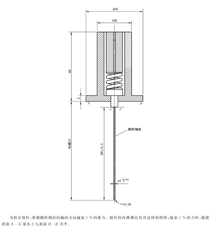
3.7 For sockets with enhanced protection, when installed and wired according to normal use requirements, live parts should be inaccessible with a 1 mm diameter probe. As shown below:
4. Grounding measures
4.1 When the plug is inserted, the grounding pin should be connected to the grounding socket first, and then the current-carrying pin should be energized. When the plug is removed, the current-carrying pin should disconnect before the ground pin disconnects.
4.2 - The ground terminal size shall be the same as the corresponding power conductor terminal size.
- The earth terminal of rewirable electrical accessories with earth contacts shall be internal.
- The earth terminal of a fixed socket-outlet shall be fixed to the base or to a component firmly fixed to the base.
- The grounding sleeve of a fixed socket-outlet shall be fixed to the base or to the cover. If fixed to the cover, the grounding sleeve shall automatically and reliably connect to the grounding terminal when the cover is in its normal position. Contacts should be silver plated or should have corrosion and wear resistance no less than silver plated.
4.3 In fixed sockets with grounding sockets, accessible metal parts that will become live when the insulation fails should be permanently and securely connected to the grounding terminal.
4.4 A socket-outlet with an IP code higher than IPXO and an insulating enclosure with more than one cable entry shall be equipped with a Internally fixed ground terminals, or providing sufficient space for floating terminals, allow incoming and outgoing connections to ensure continuity of the ground circuit.
4.5 The connection between the ground terminal and easily accessible metal parts should be a low-resistance connection, and the resistance should not be greater than 0.05Ω.
4.6 Fixed socket-outlets intended to provide a circuit that is immune to electrical interference when the equipment to which they are connected shall be equipped with a grounding socket and its terminals shall be electrically isolated from any metallic mounting or from the protective earth which may be connected to the system. electrically isolated from other exposed conductive parts of the circuit.
5.Terminals and headers
5.1 Rewirable fixed socket-outlets shall be equipped with screw-clamped terminals or screwless terminals.
5.2 Rewireable plugs and rewirable portable socket-outlets shall be equipped with terminals with threaded clamping.
5.3 If pre-soldered cords are used, it should be noted that in screw-type terminals, the pre-soldered area should be outside the clamping area when connected in normal use.
5.4 Although the parts used to clamp the conductors in the terminal can be used to maintain the terminal in the normal position or prevent the terminal from rotating, they must not be used to fix any other parts.
5.3 Thread clamp type terminal
-Threaded clamping terminals should be able to connect untreated conductors;
- Thread clamping terminals should have sufficient mechanical strength and should not be made of soft metal or metal that is prone to creep;
- Thread clamping terminals should be resistant to corrosion; thread clamping terminals should not excessively damage the conductors when clamping them;
-Threaded clamping terminals can firmly clamp the conductor between two metal surfaces;
-Thread clamping terminal, when tightening the screw or nut, it is impossible for the wires of the hard single-core conductor or the stranded conductor to come out;
-Thread clamp type terminals shall be fixed in the plug and socket in such a way that the clamping screws or nuts cannot be tightened or loosened without causing the terminal itself to loosen.
- The clamping screws and nuts of ground terminals of the thread-clamp type should be sufficiently locked to avoid accidental loosening; and should be tool-free.
-Thread clamp type earth terminals shall be such that there is no risk of corrosion arising from contact between these parts and the earthing copper conductor or other metals in contact with it.
5.4 Screwless terminals for external copper conductors
- Screwless terminals can be of a type suitable only for hard copper conductors, or of a type suitable for both hard and soft copper conductors.
- Screwless terminals shall be capable of connecting conductors that have not been specially prepared.
-Threadless terminals should be properly secured to the socket. Screwless terminals should not become loose due to the connection or disconnection of conductors during installation.
-Threadless terminals shall be able to withstand the mechanical stresses occurring during normal use.
-Threadless terminals shall be able to withstand the electrical and thermal stresses occurring during normal use.
6.1 The components of the socket sleeve should be sufficiently elastic to ensure sufficient contact pressure against the plug pins.
6.2 The parts of the socket-outlet assembly that are in contact with the pins of the plug and are used to achieve electrical connection when the plug is fully inserted into the socket shall ensure that there is metallic contact on at least two opposite sides of each pin.
6.3 The sleeve of the socket should be resistant to corrosion and wear.
6.4 Requirements for insulating liners and insulating barriers.
6.5 The socket-outlet shall be constructed to facilitate insertion of conductors and proper connection to the terminals, proper positioning of conductors, ease of securing major components to the wall or to a box, and adequate space.
6.6 The design of the socket-outlet should not prevent full mating with the relevant plug due to any protrusions from the mating surface. When the plug is inserted into the socket, it is determined by measurement that the gap between the mating surface of the plug and the socket mating surface should not exceed 1mm.
6.7 The grounding pin should have sufficient mechanical strength.
6.8 The grounding socket, phase socket and neutral socket should be locked to prevent rotation.
6.9 The metal strips of the ground circuit should not have any burrs that could damage the insulation of the power conductors.
6.10 Sockets installed in installation boxes shall be designed so that the conductor ends can be processed after the installation box is installed in the normal position but before the socket is installed in the installation box.
6.11 Cable entrances should allow entry of cable conduits or sheaths to provide complete mechanical protection for the cables.
7. Aging-resistant and moisture-proof
7.1 The socket should have aging resistance: after the sample is exposed to a temperature oven of 70℃±2℃ for 168 hours, the sample shall not have cracks and its material shall not become sticky or slippery.
7.2 The socket should be moisture-proof: after the sample is stored for 48 hours at a relative humidity of 91%~95% and a temperature of 40℃±2℃, the insulation resistance and electrical strength should comply with the regulations.
8. Insulation resistance and electrical strength
8.1 The insulation resistance between all poles connected together and the body is ≥5MΩ.
8.2 The insulation resistance between all poles is ≥2MΩ.
8.3 Apply a withstand voltage test of 50Hz, 2KV~ between all components for 1 minute. There should be no flickering or breakdown.
9. Temperature rise
After the sample has passed the life test, the temperature rise of its terminals should not exceed 45K, the maximum temperature rise of accessible metal parts should not exceed 30K, and the temperature rise of accessible non-metallic parts should not exceed 40K.
10. Breaking capacity
For electrical accessories with a rated voltage not greater than 250 V and a rated current not greater than 16 A, the stroke of the test equipment should be between 50 mm and 60 mm
Insert the plug into and out of the socket 50 times (100 strokes), the plug-in and pull-out rate is:
- For electrical accessories with a rated current not greater than 16 A and a rated voltage not greater than 250V, 30 strokes per minute;
-For other electrical accessories, 15 strokes per minute.
During the test, no sustained arc flash should occur. After the test, the specimen shall be free from damage that would affect further use, and the insertion hole for the pin shall be free from damage that would affect its safety within the meaning of this document.
11. Normal operation (life test)
Electrical accessories should be able to withstand the mechanical, electrical and thermal stresses arising from normal use without undue wear or other harmful effects. In a circuit with rated voltage, rated current, COSφ=0.8±0.05, plug and unplug 5000 times.
During the test, no continuous arc flash should occur. After the test, the specimen should not show: wear that would affect future use; deterioration of the housing, insulating gaskets or barriers, etc.; damage to the socket that would affect the normal operation of the plug; loose electrical or mechanical connections; leakage of sealant. leak.
12. Pull-out force
The socket should ensure that the plug is easy to insert and remove and prevent the plug from coming out of the socket during normal use.
13. Mechanical strength
Electrical accessories, surface-mounted installation boxes, threaded glands and covers should have sufficient mechanical strength to withstand the mechanical stress generated during installation and use.
14.1 The sample is heated in a temperature oven of 100°C ± 2°C for 1 hour. During the test, the sample should not undergo changes that would affect future use, and if there is sealant, it should not flow to expose live parts. After the test, the sign should still be legible.
14.2 After the ball pressure test, the indentation diameter shall not exceed 2mm.
15.Screws, current-carrying parts and their connections
15.1 Both electrical and mechanical connections should withstand the mechanical stresses occurring in normal use.
15.2 For screws that engage the threads of insulating materials and screws that need to be tightened when connecting electrical accessories during installation, ensure that they are correctly guided into the screw holes or nuts.
15.3 Electrical connections should be such that contact pressure is not transmitted through the insulating material.
15.4 Screws and rivets should be locked when making electrical connections and mechanical connections to prevent loosening and rotation.
15.5 Metal current-carrying parts should be made of metal that meets the requirements for mechanical strength, electrical conductivity and corrosion properties.
15.6 Contacts that will slide during normal use should be made of corrosion-resistant metal.
15.7 Self-tapping and self-cutting screws shall not be used to connect current-carrying parts. They may be used for earth connections, provided that at least two screws are used.
16.Creepage distance, electrical clearance, through insulation sealing distance
Creepage distance, electrical clearance and distance through sealant are as follows:
17.Abnormal heat and flame resistance of insulating materials
17.1 Glow wire test (tested in accordance with clauses 4 to 10 of BS6458-2.1:1984) Insulating materials for fixed current-carrying parts and grounded circuit parts 850℃
17.2 Insulating materials of non-fixed current-carrying parts and grounded circuit parts 650℃.
17.3 After the test, there is no visible flame and no continuous glow, or the flame is extinguished or the glow is lost within 30 seconds after the glow wire is removed; the tissue paper does not catch fire, and the pine board does not burn.
18.Anti-rust performance
Iron parts shall not show rust after passing the corrosion test.
Post time: Feb-05-2024