


According to CNN, the number of victims of the Bronx apartment fire in New York City Mayor Eric Adams on January 9, local time, was 17, including 9 adults. and 8 children reported that based on evidence at the scene and eyewitness testimony, it was initially determined that the fire was caused by the resident using a "malfunctioning" space heater in the bedroom.
Our country's mandatory standard for special safety requirements for indoor heaters for household and similar purposes is equivalent to IEC 60335-2-30: 2004, which makes corresponding requirements for electric heaters.
Electric heater inspection
1. Protection against contact with live parts
2. Input power and current
3. Fever
4. Leakage current and electrical strength at operating temperature
5. Transient overvoltage
6. Moisture resistant
7. Leakage current and electrical strength
8. Overload protection of transformers and related circuits
9. Stability and mechanical hazards
10. Mechanical strength
11. Internal wiring
12. Grounding measures
13. Clearances, creepage distances and solid insulation
14. Heat and flame resistant
1.Protection against contact with live parts
The construction and enclosure of the appliance shall provide adequate protection against accidental contact with live parts.
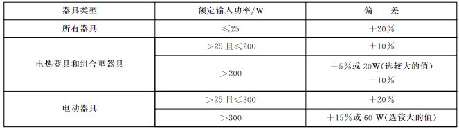
2.Input power and current
If the appliance is marked with a rated power input, the power input of the appliance shall not deviate from the rated power input by more than the deviation shown in the table below at normal operating temperature.
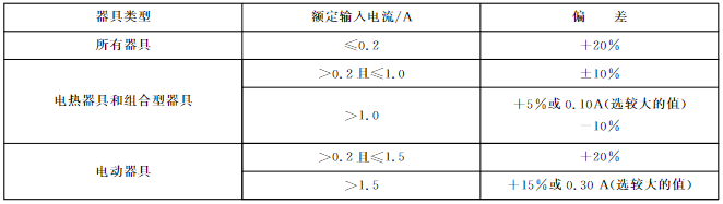
If the appliance is marked with a rated current, the current at normal operating temperature shall not deviate from the rated current by more than the corresponding deviation value given in the table below.
3. Fever
During normal use, the appliance and surrounding environment should not reach excessive temperatures.
4. Leakage current and electrical strength at operating temperature
4.1 At operating temperature, the leakage current of the appliance should not be excessive, and its electrical strength should meet the specified requirements. Electric heating appliances operate at 1.15 times the rated input power. Electric appliances and combination appliances are powered at 1.06 times the rated voltage. The installation instructions specify that three-phase appliances from a single-phase supply may also be used and the three circuits connected in parallel may be tested as single-phase appliances. Disconnect the protective impedance and radio interference filter before carrying out this test.
After the appliance continues to operate for a length of time corresponding to the most adverse conditions in normal use, the leakage current shall not exceed the following values:
- 0.25 mA for Class II appliances
-0.5mA for Class 0, OI and dishware appliances
- 0.75 mA for Class I portable appliances
- 3.5mA for Class I stationary electric appliances
- For Class I stationary electric heating appliances, 0.75mA or 0.75 mA/kW (rated input power of the appliance), whichever is larger, but the maximum is 5mA
For combined appliances, the total leakage current may be within the limits specified for electric heating appliances or electric appliances, whichever is larger, but the two limits cannot be added.
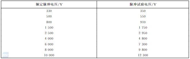
5.Transient overvoltage
The appliance shall be able to withstand transient overvoltages to which it may be subjected. Determine whether it is qualified by performing a pulse voltage test on each gap smaller than the value specified in the table below.
6. Moisture resistant
Appliance enclosures shall provide an appropriate level of waterproofing.
7. Leakage current and electrical strength
The leakage current of the appliance should not be excessive, and its electrical strength should meet the specified requirements.
The AC test voltage is applied between live parts and accessible metal parts connected to the metal foil. The area of the connected metal foil does not exceed 20cmx10cm, and it is in contact with the accessible surface of the insulating material.
Test voltage:
- For single-phase appliances, 1.06 times the rated voltage;
- For three-phase appliances, 1.06 times the rated voltage divided by /3.
Within 5 seconds after applying the test voltage, measure the leakage current.
Leakage current should not exceed the following values:
- For Class II appliances: 0.25 mA
- For Class 0, Class 0I and Sichuan Class appliances: 0.5mA
- For Class I portable appliances: 0.75mA
- For Class I stationary electric appliances: 3.5mA
- For Class I stationary electric heating appliances: 0.75mA or 0.75mA/kW (rated input power of the appliance), whichever is greater,
But the maximum is 5mA.
If all controllers have an open position in all poles, the value specified above for the leakage current limit is doubled. The leakage current limit specified above shall also be doubled if:
- There is only one thermal circuit breaker on the appliance and no other controls, or
- All thermostats, temperature limiters and energy regulators do not have an off position, or
-The appliance is equipped with a radio interference filter. In this case, the leakage current when disconnecting the filter should not exceed the specified limit.
For combined appliances, the total leakage current may be within the limits for electric heating appliances or electric appliances, whichever is the larger limit, but the two limits cannot be added together.
Immediately after the above test, the insulation is subjected to a voltage of a fundamental sinusoidal wave with a frequency of 50 Hz or 60 Hz for 1 min.The following table gives
Test voltage values applicable to different types of insulation are given. Accessible parts of the insulation material should be covered with metal foil.
8. Overload protection of transformers and related circuits
Appliances having a circuit powered by a transformer shall be constructed in such a way that excessive temperatures do not occur in the transformer or in circuits associated with the transformer when a short circuit might occur during normal use.
Compliance is determined by applying the most adverse short-circuit or overload conditions likely to occur in normal use. The supply voltage of the appliance is 1.06 times or 0.94 times the rated voltage, whichever is more unfavorable. The temperature rise value of the insulation layer of wires in safety extra-low voltage circuits should not exceed 15K of the relevant specified value in Table 3.
9. Stability and mechanical hazards
Portable heaters should be sufficiently stable. Heaters equipped with appliance sockets must be equipped with a cord assembly. Place the heater at an angle of 15° to the horizontal in the most unfavorable position for normal use. The heater should not tip over.
A heater with a mass exceeding 5 kg is placed on a horizontal surface and a force of 5N + - 0.1N is applied to the top of the heater in the most unfavorable horizontal direction. The electric heater should not tip over.
10. Mechanical strength
Appliances shall have adequate mechanical strength and shall be constructed to withstand rough treatment and handling likely to occur in normal use. Use a spring impactor to conduct an impact test on the appliance. The appliance is rigidly supported and an impact energy of 0.5J is impacted three times on every possible weak point of the appliance shell.
For heaters whose heating elements are in direct contact with the glass panel, a spring impactor should be used to impact the panel, and the impact energy is 2 J.
Visibly emitting radiant heaters, except those installed at high positions, should be placed so that the central part of the fire protection cover is in a horizontal position. Place a flat-bottomed weight with a mass of 5 kg and a diameter of 100 mm in the center of the fire protection cover for 1 min. After the test, the fire protection cover shall show no significant permanent deformation.
11. Internal wiring
Routing paths should be smooth and free of sharp edges. The wiring should be protected so that they do not come into contact with burrs, cooling fins or similar edges that could cause damage to the insulation. Metal holes through which insulated wires pass should have a flat, rounded surface or an insulating sleeve. The wiring should be effectively prevented from coming into contact with moving parts, and its suitability should be determined by visual inspection.
- Insulating beads and similar ceramic insulators on live conductors shall be fixed or supported so that they cannot change position or rest on sharp corners. If the insulating beads are in a flexible metal conduit, they shall be enclosed in an insulating sleeve unless the conduit cannot move during normal use. Compliance is determined by inspection and manual testing.
- Different parts of the appliance that are capable of moving relative to each other during normal use or user maintenance shall not cause undue stress on electrical connections and internal conductors, including conductors providing earth continuity. Flexible metal conduits shall not cause damage to the insulation of the conductors contained within them. Open coil springs cannot be used to protect conductors. If a coil spring with contacting coils is used to protect a conductor, a suitable insulating lining must be added to the insulation of the conductor.
- If bending occurs during normal use, place the appliance in its normal position for use and supply it with rated voltage under normal operating conditions. The movable parts move forward and backward to bend the wire within the maximum angle allowed by the structure. The bending rate is 30 times/min. The number of bends is:
For wires that will bend during normal operation, 10,000 times;
100 times for wires that are bent during user maintenance.
- Exposed internal wiring shall be rigid and shall be secured so that in normal use creepage and clearance distances cannot be reduced below the specified values.
-The insulation of internal wiring should be able to withstand the electrical stresses that may occur during normal use. The electrical performance of basic insulation should be equivalent to the basic insulation of flexible wires specified in GB 5023.1 or GB 5013.1, or comply with the following electrical strength test.
- Apply a voltage of 2000V between the wire and the metal foil wrapped outside the insulation layer for 15 minutes. There should be no breakdown.
-When bushing is used as additional insulation for internal wiring, it shall be held in place by a reliable means.
Compliance is checked by inspection and by manual test.
- The yellow/green two-color marked conductor should be used only as a grounding conductor. Compliance is determined by inspection.
12. Grounding measures
- Accessible metal parts of Class OI and Class I appliances that may become live in the event of insulation failure shall be permanently and reliably connected to an earth terminal within the appliance, or to an earth contact at the appliance input socket.
-The ground terminal and ground contact should not be connected to the neutral terminal.
Class 0, Class II and Sichuan appliances shall not have grounding measures. Safety extra-low voltage circuits should not be connected to earth unless they are protective extra-low voltage circuits. Compliance is determined by inspection.
-The clamping device of the ground terminal should be sufficiently secure to prevent accidental loosening.
For other structures, special measures may be necessary, such as the use of a component that cannot be dismantled by accidental neglect.
Terminals used for connecting external equipotential conductors shall allow the connection of conductors with a nominal cross-sectional area from 2.5 mm2 to 6 mm2, and it shall not be used to provide earth continuity between different parts of the appliance. It should not be possible to loosen these wires without the help of tools. Compliance is determined by inspection and manual testing.
- If a detachable part with an earth connection is inserted into another part of the appliance, its earth connection shall be made before the current-carrying connection and when the part is withdrawn, the earth connection shall be broken after the current-carrying connection is disconnected.
For appliances with a power cord, the length of the conductor between the terminal or cord fixture and the terminal shall be such that if the cord slips out of the cord fixture, the current-carrying conductor will be taut before the grounding conductor. Compliance is determined by inspection and manual testing.
- All parts of earth terminals intended for connection to external conductors shall be free from any risk of corrosion arising from contact with the copper of the earth conductor, or from contact with other metals.
Parts used to provide earth continuity shall be of metal of adequate corrosion resistance, except for metal frame or enclosure parts. If these parts are made of steel, a plating thickness of at least 5 μm shall be provided on the surface of the body. Coated or uncoated steel parts intended only to provide or transmit contact pressure shall be adequately protected against rust.
If the body of the earth terminal is part of a frame or enclosure made of aluminum or aluminum alloys, precautions should be taken to avoid the risk of corrosion arising from contact of copper with aluminum or aluminum alloys. Compliance is determined by inspection and measurement.
- The connection between the ground terminal or ground contact and the grounded metal part shall have a low resistance value.
This requirement does not apply to connecting devices providing earth continuity in protected extra-low voltage circuits if the clearances for basic insulation in protected extra-low voltage circuits are specified based on the rated voltage of the appliance.
-Printed traces on printed circuit boards in hand-held appliances shall not be used to provide ground continuity. Earth continuity may be provided in other appliances if the following conditions are met:
- There are at least two lines with independent solder joints, and the requirements of 27.5 should be met for each circuit appliance;
-The material of the printed circuit board complies with the requirements of IEC 60249-2-4 or IEC 60249-2-5.
Compliance is determined by inspection and relevant tests.
13. Clearances, creepage distances and solid insulation
Appliances shall be constructed so that clearances, creepage distances and solid insulation are adequate to withstand the electrical stresses to which the appliance may be subjected.
If coatings are used on printed circuit boards to protect the microenvironment (Class A coatings) or to provide basic insulation (Class B coatings), Appendix J applies. Level 1 contamination is deposited in microenvironments using Class A coatings. When using Class B coating, there are no requirements for electrical clearances and creepage distances.
- Taking into account the rated impulse voltages of the overvoltage categories in Table 15, the clearances shall not be less than the values specified in Table 16, unless the clearances between basic insulation and functional insulation meet the impulse voltage test of Chapter 14. However, if the distance in the structure is affected by wear, deformation, component movement or assembly, the corresponding electrical clearance should be increased by 0.5mm when the rated pulse voltage is 1500V or higher, and the pulse voltage test is not applicable.
14. Heat and flame resistant
For external parts made of non-metallic materials, parts of insulating material used to support live parts (including connections), and parts of heat-shrinkable material that provide accessory insulation or reinforced insulation,
The United States, Canada, the European Union and Australia all have their own safety standards for such products. Especially Amazon 3 stations have special requirements.
American standard: UL 1278
Canadian Standard: CSA C22.2 No.46
EU standard: EN 60335-2-30
British Standard: BS EN 60335-2-30
International standard: IEC 60335-2-3
Australian Standard: AS/NZS 60335.2.30
Post time: Dec-29-2023